boat electrical box 004

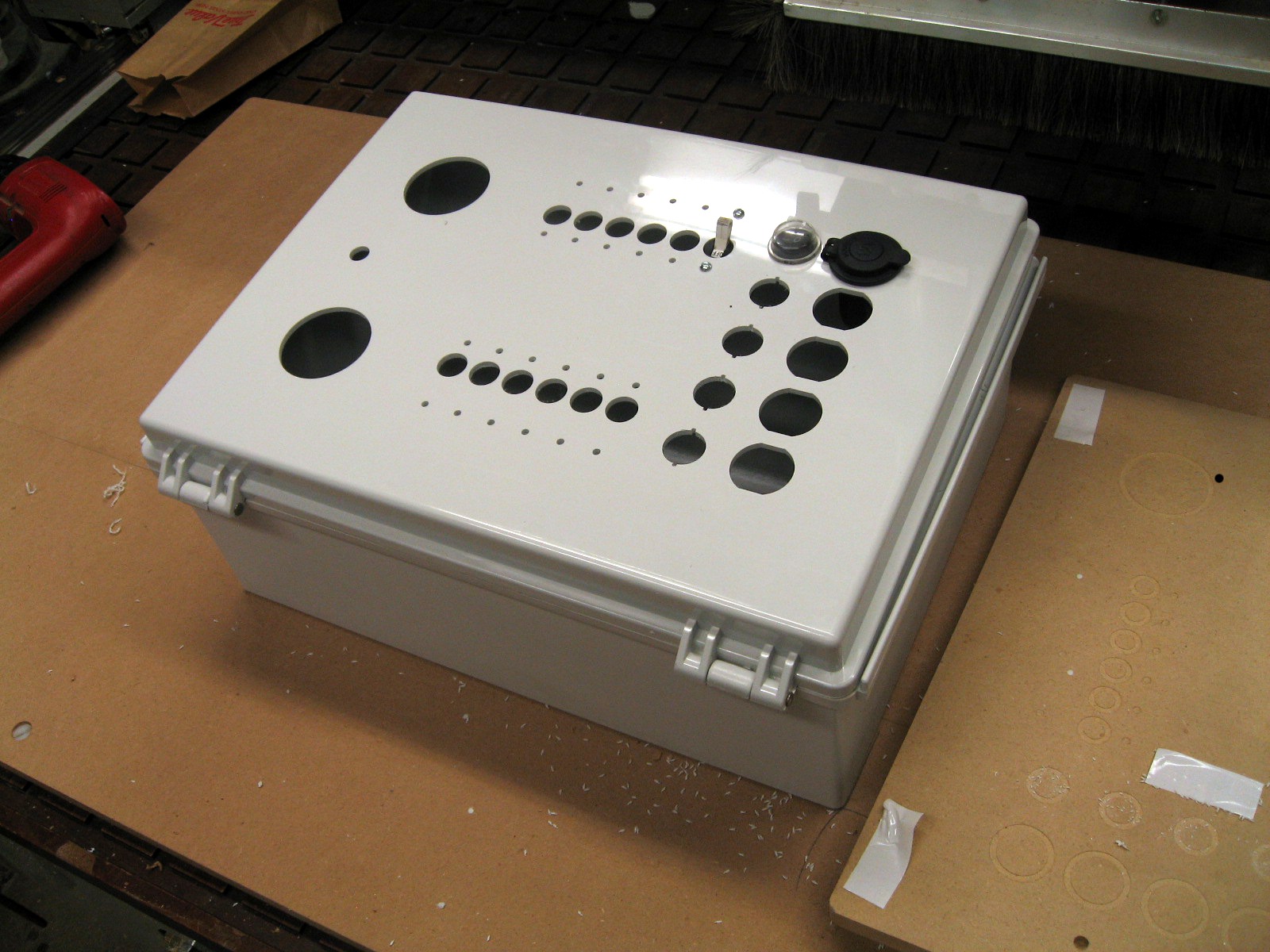
David Heiserrer, of Jiggernaut  fame is renovating a sailboat, and part of the renovation involves some new  electrical doodads, so he emailed me a file and dropped off the electrical box you see in the picture above, except it had none of those holes in it.

How to mount such a thing on the table for cutting? The four mounting holes on the back with threaded inserts looked like a good bet. It turned out to be a standard polycarbonate enclosure from Hoffman, so a datasheet showing the spacing of the mounting hole spacing was pretty easy to turn up.

boat electrical box 001

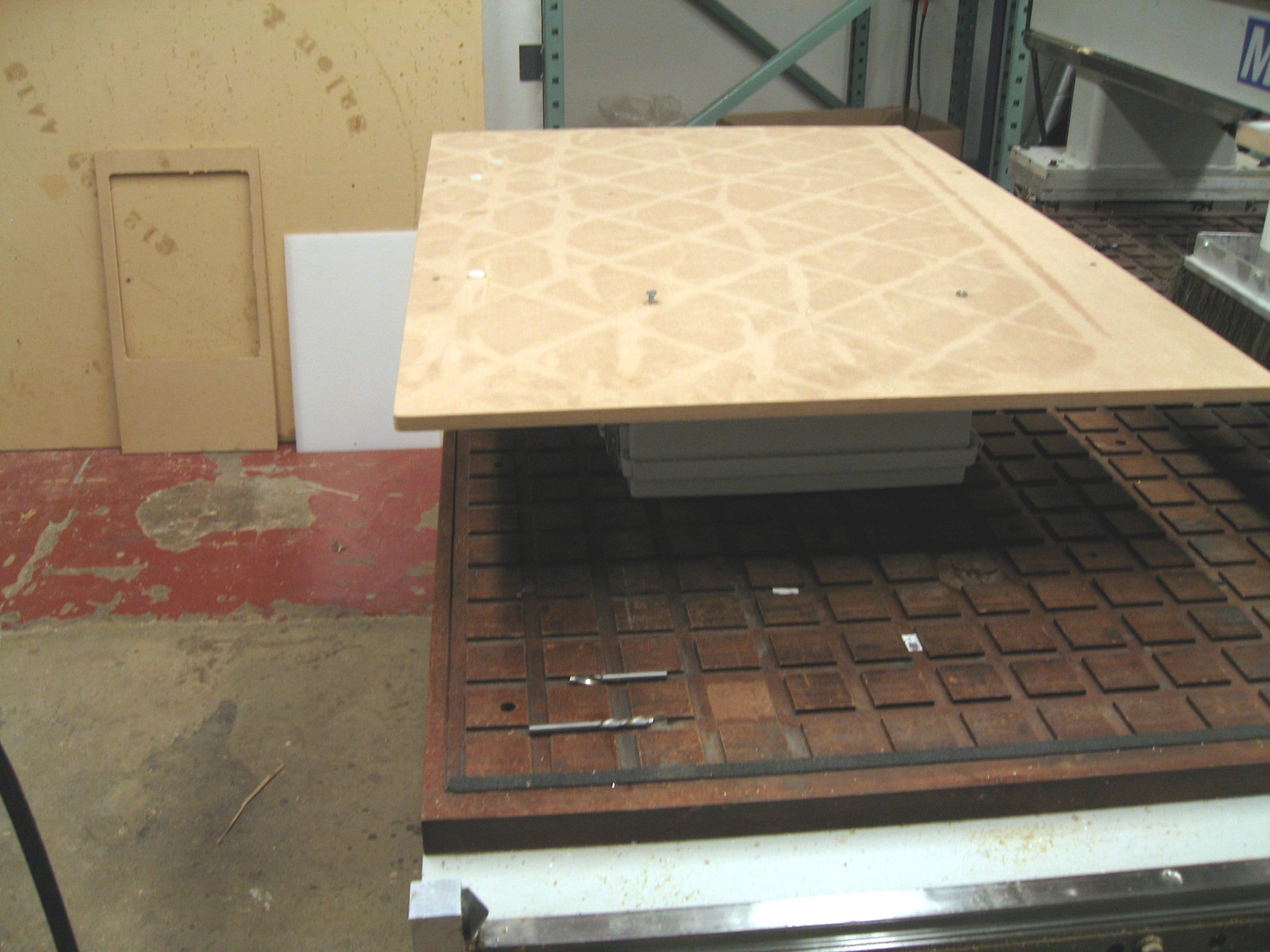
It was the perfect opportunity to do something useful with an oil-stained piece of half inch MDF that was sitting around. I quickly programmed and drilled the rather oddly spaced hole pattern and mounted the board to the back of the enclosure using flathead screws, then mounted the board to the machine.

boat electrical box 003


Experience has shown that an unsupported piece of plastic like the door (where I needed to do the cutting) will vibrate like a drumhead, so I also cut another piece of half inch MDF to fit inside the door to back it up and attached it with double sided tape.

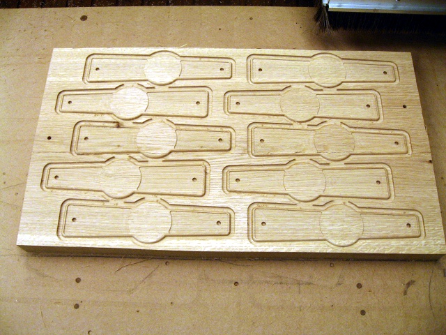
David’s original design had round holes for all the components, but he brought samples. A little quick googling turned up datasheets for all of them, so I fine tuned the dimensions and added anti rotation features.

boat electrical box 005


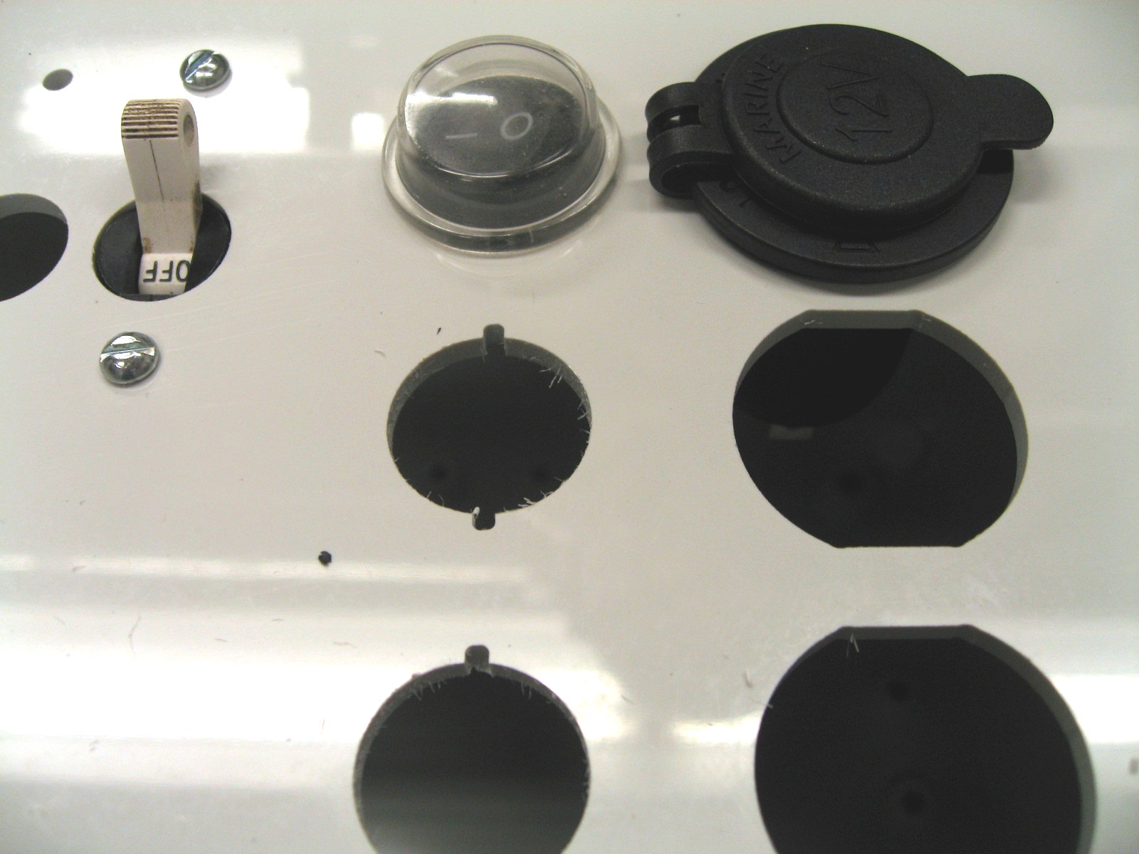
David now has a very high quality electrical box with parts that will remain neatly aligned. It doesn’t matter whether I have to think inside the box, outside the box, or both, my focus is always on creative solutions to my customers problems!

easy as one two three…

First you start with a couple of big old rough sawn white oak planks:

edge 017

Then you cut them up with a CNC router:

edge 025-enhanced

Then you do some finishing and assembly, and what you wind up with is, Indeed, a welcome sight to Minnesota beer drinkers:

IMG_3850-cropped

This particular specimen was found in the wild at Uptown eating and drinking establishment Muddy Waters.

I cut the letters, Sean did the rest

Forgot to take pictures of these sign letters while they were being cut, but here they are assembled to the steel backing. The material was 3/4″ Extira, a variety of MDF (medium density fiberboard) with outstanding weather resistance, which is also used for exterior architectural trim and moldings.

The picture above shows the twin of the sign in the first picture in place and mounted to the building. The design, assembly, and mounting were done by the very capable Sean Doyle.  He also cut the delicate tree design on the corner of the building, which is visible above his left shoulder by hand with an oxyacetylene torch. The rest of us can only dream  of having such well developed fine motor skills.

fun with HDPE

Interesting little parts made from HDPE. I probably shouldn’t tell what they’re for yet. This started out as a DXF file from an ancient version of Adobe Illustrator which was emailed and imported just fine.

A quick wave of the heat gets rid of a lot of the scuffing and scratching on the original surface of the sheet, much like flame polishing acrylic. The rounded over edges are easily done on the CNC router.

I wound up running these in 12″ by 24″ sheets that yielded 48 parts per sheet.

deep foam

Prototype foam parts. About 5 inches deep at the lowest point. Coffee cup shows scale. This is a test cut made in cheap one-pound foam from the lumberyard. The yellow lines are where the two-inch sheets were glued up with urethane foam.

Here it is flipped over after cutting the bottom side.

And here is the finished part, cut free from the frame.

Reuleaux triangle

If you think this looks like just another useless desk, toy, you are sooo wrong! It’s actually a sample to demonstrate  my plastic cutting capabilities. I was perusing Thingiverse looking for inspiration, and found this version, which at number 1082 appears to be a pretty early thing.

I liked the Reuleaux triangle because it incorporates some interesting geometrical concepts. Here’s a diagram to illustrate:

It just so happens that this shape rolls around nicely inside an appropriately sized square, as the following animated gif illustrates:

It’s a  principle which has actually been utilized to drill square holes. Click here to see the Wikipedia entry. Reuleaux, in spite of his French-sounding name, was actually a German engineer who did pioneering work in kinematics.

Here’s one last macro shot of my sample, showing the chamfer cut on the recesses where the nuts fit:

The nuts which fit in these recesses are 10-24 thread size, and are 3/8 of an inch across. Those toolmarks on the bottom are from an eighth inch diameter bit.

The plan is to put promotional engraving on these, check back for examples!


stuff you can’t do with a laser

Lasers work well for cutting plastics- they’re fast and accurate, and leave a nice shiny edge, which is usually a good thing. There are however some drawbacks. Those nice looking shiny edges can develop cracks when glued, because they have stress “baked in” by the laser.

And you also can’t  add 3D features like this nut pocket:

With a router you can also add bevels to the edges of a part like this:

The part  in the picture above is made from extruded acrylic. It doesn’t machine quite as nicely as the cast acrylic in the first two pictures, but with good sharp tools and appropriate cutting strategies it can be cut quite well.

If you have parts that were already cut on a laser and need some additional features added to  them I can definitely help.

small machining job

My friend John Scherer is an active member of local hackerspace TCMaker and he is building a super sturdy small CNC router on a shoestring budget. They don’t have a milling machine there, so I helped him out.

The rails themselves are aluminum extrusions with what looks like 4 steel rods embedded where the ball bearings contact the rail. Very clever.

The plan was to mount them to the 80/20 style extrusions, but as can be seen from the photo above, the channel  neede to be widened a bit for the extrusion to sit flat. Holes needed to be drilled through the 80/20 for mounting screws, and steel backing plates made, since the 80/20 is thin in the center.

Here’s the 80/20 being drilled on the trusty Bridgeport:

This photo shows the individual parts in front, and an assembled unit behind it:

This view from the end shows the steel backing plate installed:


twist removal

One very frustrating situation for a woodworker is having an otherwise nice board which has acquired a bit of a twist along it’s length. Feeding it through a planer won’t get it out. Even if you have a jointer wide enough, it still takes quite a bit of skill and time to remove the twist.

The CNC router makes short work of it.  I enhanced this image a bit to make it easier to see the gap under the closest corner of the board. This was before the board was surfaced, the thickness is pretty uniform.

Here is a picture of the other end after surfacing. The top surface is now flat, the difference in thickness from left to right shows how twisted it was. I then flipped it over and cut it to uniform thickness. If you had a pile of twisted boards to flatten out, you might just flatten one side on the CNC router, and then feed them through a planer. Actually any piece of wood that would fit on the four foot square table and under the 6 inch gantry could be easily made flat as a pool table. This could include a big slab of a tree or a butcher block.

And last (but not least) is the cutter which makes it possible. The carbide tips (inserts) which do the actual cutting are only about 2 bucks each and have 4 usable cutting edges.

The Bird

Here’s an example of the kind of 3D carvings which can be done on my CNC router:


This 3D object began life as a 2D drawing:


A bit of digital massaging transformed the 2D drawing above into a machinable 3D object. I used 2 pieces of totally free cross platform software, GIMP, and Blender3D to create the 3D object, to demonstrate that you don’t need software costing thousands of dollars to create something I can cut for you.

When it comes to creating the “G-code” that tells the machine exactly what to do and where, there isn’t really any good free software yet, so I use commercial software called  MeshCAM. In the picture below you can see the object loaded in MeshCAM, and ready to codes for the machine. It’s called an “STL” file, and it’s made up entirely of tiny triangles. Bazillions of them. The blue line in the center lets you know which way is up.


All those fine green lines show where the tip of the tool is going to go. This is called a “toolpath”. Typically a job like this will have at least two toolpaths, a “rough” cut and a “finish” cut. The close distance between the lines in the image above shows this is a finishing toolpath. The closer the lines, the finer the finish, and the more time it takes to complete.

The program was test cut first in insulation foam, since it’s cheap, easy on cutters, and cuts quickly. The finishing toolpath has smoothed out the area in the bottom half of the photo, while the ridges from the roughing toolpath are still visible in the top half.